Table of contents
Open Table of contents
Visual Demonstration (Project Video)
Project Requirements:
This project involves turning a wand into a gesture controller, similar to Harry Potter’s wizard wand. Different gestures or movements with the wand trigger various effects on a screen or LEDs. The project requires the following components:
- Arduino board
- Analog sensors
- LEDs
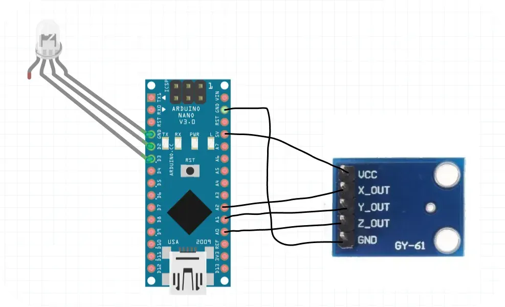
- Accelerometer or gyroscope sensor for detecting movement. Example: GY-61 sensor detecting movement Arduino GY-61 sensor detecting movement Arduino
Arduino Wiring Diagram:
Arduino Code Explanation:
In the Arduino code, I utilize analog sensors connected to pins A0 and A1 to gather data. Two pins, 2 and 3, are configured as outputs for controlling external devices, likely LEDs in this scenario. The setup() function initializes serial communication at a baud rate of 9600. Within the loop() function, sensor readings are obtained from A0 and A1. These values are printed over the serial connection.
int AnalogPin0 = A0; // Declare variable for analog pin 0
int AnalogPin1 = A1; // Declare variable for analog pin 1

void setup() {
  pinMode(2, OUTPUT); // Configure pin 2 as output
  pinMode(3, OUTPUT); // Configure pin 3 as output
  Serial.begin(9600); // Start serial communication at 9600 baud rate
}

void loop() {
  int sensorValue0 = analogRead(A0); // Read sensor value from A0
  int sensorValue1 = analogRead(A1); // Read sensor value from A1
  int sensorValue2 = analogRead(A2); // Read sensor value from A2 (commented out)

  Serial.print(sensorValue0); // Print sensor value 0
  Serial.print(",");
  Serial.print(sensorValue1); // Print sensor value 1
  Serial.print(",");
  Serial.print(sensorValue2); // Print sensor value 2
  Serial.print(",");
  Serial.println();

  digitalWrite(2, HIGH);   // Turn on LED connected to pin 2
  delay(sensorValue0);     // Delay based on sensor value 0
  digitalWrite(2, LOW);    // Turn off LED connected to pin 2
  delay(sensorValue1);     // Delay based on sensor value 1
  digitalWrite(3, LOW);    // Turn off LED connected to pin 3
  delay(random(sensorValue1, sensorValue0)); // Random delay between sensor values
  digitalWrite(3, HIGH);   // Turn on LED connected to pin 3
  delay(sensorValue2);     // Delay based on sensor value 2
}
Processing Code Explanation:
I then define three classes: Particles, Particle and ParticleSystem. The Particle class represents individual particles in our system, each with attributes such as velocity and lifespan. The ParticleSystem class manages a group of particles, updating and displaying them on the screen.
Particles Class:
The background color is set based on the sensor readings, and the emitter position is updated accordingly. The ParticleSystem object is updated and displayed, creating a dynamic visual effect.
// Particles class
import processing.serial.*; //import the Serial library

int end = 10;    // the number 10 is ASCII for linefeed (end of serial.println), later we will look for this to break up individual messages
String serial;   // declare a new string called 'serial' . A string is a sequence of characters (data type know as "char")
Serial port;  // The serial port, this is a new instance of the Serial class (an Object)
ParticleSystem ps;
PImage sprite;

int result1;
int result2;
int result3;

void setup() {
  size(1500, 980, P2D);
  orientation(LANDSCAPE);
  sprite = loadImage("sprite-wand.png");
  ps = new ParticleSystem(10000);

  port = new Serial(this, Serial.list()[2], 9600); // initializing the object by assigning a port and baud rate (must match that of Arduino)
  port.clear();  // function from serial library that throws out the first reading, in case we started reading in the middle of a string from Arduino
  serial = port.readStringUntil(end); // function that reads the string from serial port until a println and then assigns string to our string variable (called 'serial')
  serial = null; // initially, the string will be null (empty)

  // Writing to the depth buffer is disabled to avoid rendering
  // artifacts due to the fact that the particles are semi-transparent
  // but not z-sorted.
  hint(DISABLE_DEPTH_MASK);
}

void draw () {
    while (port.available() > 0) { //as long as there is data coming from serial port, read it and store it
    serial = port.readStringUntil(end);
  }
    if (serial != null) {
     String[] a = split(serial, ',');  //a new array (called 'a') that stores values into separate cells (separated by commas specified in your Arduino program)
     println(a[0]); //print Value1 (in cell 1 of Array - remember that arrays are zero-indexed)
     println(a[1]); //print Value2 value
     println(a[2]); //print Value2 value

     result1 = Integer.parseInt(a[0]);
     result2 = Integer.parseInt(a[1]);
     result3 = Integer.parseInt(a[2]);
    }

    // random background between 1 to 200, background between 190 to result2,  background between 55 to result3,
    background(max(1, min(200, result1)), max(1, min(90, result2)), max(1, min(55, result3)));

    // Print message with background values
    System.out.println("Background is = " + max(1, min(200, result1)) + ", " + max(1, min(190, result2)) + ", " + max(1, min(55, result3)));

    ps.update();
    ps.display();

    ps.setEmitter(max(result1, min(result2, result3)), result2);
    System.out.println("Emitter is = " + max(result1, min(result2, result3)) + ", " + result2);

    fill(255);
    textSize(16);
    text("Frame rate: " + int(frameRate), 10, 20);
}
Particle Class:
In the setup() function, I initialized the serial connection and create a ParticleSystem object. The draw() function continuously reads data from the serial port, updates the particle system, and adjusts visual elements based on the received data.
class Particle {
  PVector velocity;
  float lifespan = 255;
  PShape part;
  float partSize, partSize1, partSize2;

  PVector gravity = new PVector(0,0.1);

  Particle() {
    //Part size
    partSize1 = random(10,25);
    partSize2 = random(40,70);
    partSize = random(min(partSize1, min(40, partSize2)), partSize2);

    // part shape
    part = createShape();
    part.beginShape(QUAD);
    part.noStroke();
    part.texture(sprite);
    part.normal(0, 0, 1);
    part.vertex(-partSize/2, -partSize/2, 0, 0);
    part.vertex(+partSize/2, -partSize/2, sprite.width, 0);
    part.vertex(+partSize/2, +partSize/2, sprite.width, sprite.height);
    part.vertex(-partSize/2, +partSize/2, 0, sprite.height);
    part.endShape();

    rebirth(width/2,height/random(3, 5.5));
    lifespan = random(255);
  }

    PShape getShape() {
    return part;
  }

  void rebirth(float x, float y) {
    float a = random(TWO_PI);
    // speed of the particles exploding from 0.5, 4 is default
    float speed = random(min(partSize1, max(0.5, 4), 6));

    velocity = new PVector(cos(a), sin(a));
    velocity.mult(speed);
    lifespan = 255;
    part.resetMatrix();
    part.translate(x, y);
  }

  boolean isDead() {
    if (lifespan < 0) {
     return true;
    } else {
     return false;
    }
  }

  public void update() {
    lifespan = lifespan - 1;
    velocity.add(gravity);

    part.setTint(color(255,lifespan));
    part.translate(velocity.x, velocity.y);
  }
}
Finally, ParticleSystem Class:
class ParticleSystem {
  ArrayList<Particle> particles;

  PShape particleShape;

  ParticleSystem(int n) {
    particles = new ArrayList<Particle>();
    particleShape = createShape(PShape.GROUP);

    for (int i = 0; i < n; i++) {
      Particle p = new Particle();
      particles.add(p);
      particleShape.addChild(p.getShape());
    }
  }

  void update() {
    for (Particle p : particles) {
      p.update();
    }
  }

  void setEmitter(float x, float y) {
    for (Particle p : particles) {
      if (p.isDead()) {
        p.rebirth(x, y);
      }
    }
  }

  void display() {

    shape(particleShape);
  }
}
This combined Arduino and Processing setup allows for real-time interaction between hardware and visual elements, creating dynamic and responsive experiences.
References
-
Arduino Documentation. Retrieved from [ https://docs.arduino.cc/learn/]
-
Processing Documentation. Retrieved from [ https://processing.org/reference/]